SLD Style Editor
- Kim Stimpson
- Tom Chadwin
5.4.0+
In order to see data on a map, it must be styled. Styling specifies colour, thickness, and other visible attributes used to render data on a map. Styling is accomplished using a markup language called Styled Layer Descriptor, or SLD for short. SLD is an XML-based markup language and is extremely powerful.
Vector data in iShare consists of three classes of shapes: Points, Lines, and Polygons. Lines, one dimensional, are the simplest, as they have only the edge to style (aka Stroke). Polygons, two dimensional, have an edge and an inside (aka Fill), both of which can be styled differently. Points can have a Stroke, Fill and Size that can be styled.
The SLD Style Editor (introduced in V5.4.0) allows you to change the style of your OGC Layer without having to manually edit the SLD. This may be accessed by clicking the Modify Style button when selecting an OGC Layer in Studio. For advanced users there is still the Advanced tab where you may manually edit.
If you manually edit the SLD via the Advanced tab and you add entries that cannot be handled by the SLD Style Editor then the Advanced tab will be your only option.
The default style for the Geometry type you selected will be displayed for you to make your changes. Due to the flexibility of MapServer not all of the options will be available with all of the various types of symbol; we suggest that you try various different options to see which gives you the effect you require.
The list of symbols is taken from the SYMBOLSET defined in your .map file. See Symbols & Styling.
The following table shows the Individual Configuration Settings for each geometry type - the Shared Configuration Settings are defined afterwards. You should see the sample map changing as you make your configuration changes so that you can see how your geometry will be displayed in iShare; for each geometry type you will see one example near the centre of the map. If a change does not affect the geometry of the example on the map then it could be that it is not available for the symbol you have selected. Once you are happy with your configuration changes click OK to apply them or Cancel to return to Studio without updating.
Individual Configuration Settings
| Point | Polygon | Line |
|---|---|---|
|
|
|
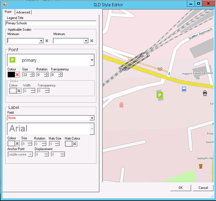
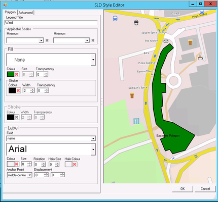
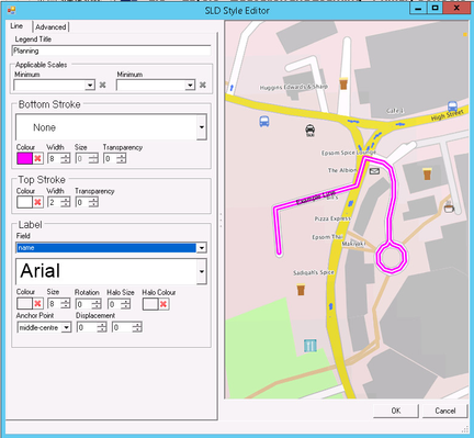
PointFirst pick the symbol that you wish to use for your point from the drop down selection. Colour To revert to the default colour (black) click on the red cross. To select a colour click on the space to the left of the red cross and the Colour pallet will be displayed. Pick your colour and click OK. If you have picked an icon then it will not be affected by the colour you select. Size To alter the size of the point either use the scroll buttons or manually enter the size in the box provided. Rotation If you wish to rotate the point symbol you may enter a value here. 0 means no rotation. Transparency If you wish to alter the transparency for the point symbol you may enter a value here. 0 means no transparency. Stroke This option is only available if you have picked a vector symbol for your point. You may change the Colour, Width and Transparency for the stroke in the same way as you can for the actual point. | FillIf you wish to use a symbol for your fill then select one from the drop down selection or for a colour fill leave this entry as None. Colour To revert to the default colour (grey) click on the red cross. To select a colour click on the space to the left of the red cross and the Colour pallet will be displayed. Pick your colour and click OK. Size To alter the size of the fill symbol either use the scroll buttons or manually enter the size in the box provided. Transparency If you wish to alter the transparency for the fill symbol you may enter a value here. 0 means no transparency. Stroke This option is only applied if you have picked a fill symbol that has been defined in the .map file with "FILLED TRUE". This will apply a stroke to the fill symbol you have selected. You may change the Colour, Width and Transparency for the stroke in the same way as you can for the actual fill symbol. StrokeThis is where you may select the outline (stroke) for your polygon. Colour To remove the colour entirely click on the red cross. To select a colour click on the space to the left of the red cross and the Colour pallet will be displayed. Pick your colour and click OK. Width To alter the width of the stroke line either use the scroll buttons or manually enter the width in the box provided. Transparency If you wish to alter the transparency for the stroke you may enter a value here. 0 means no transparency. | Bottom StrokeIf you wish to use a symbol for your Bottom stroke then select one from the drop down selection or for a colour fill leave this entry as None. Colour To remove the colour entirely click on the red cross. To select a colour click on the space to the left of the red cross and the Colour pallet will be displayed. Pick your colour and click OK. Width To alter the size of the stroke either use the scroll buttons or manually enter the size in the box provided. Normally the Bottom stroke should be wider than the Top otherwise it will not be seen. Size This option is only available if you have selected a symbol for your stroke. To alter the size of the symbol either use the scroll buttons or manually enter the size in the box provided. Transparency If you wish to alter the transparency for the stroke you may enter a value here. 0 means no transparency. Top StrokeThe options here are the same as for the Bottom stroke defined above. Normally the width of the Top stroke should be smaller than the width of the Bottom stroke in order for it to be visible. |
Shared Configuration Settings
Legend Title
This is the text that will appear in the Legend.
Applicable Scales
Here you may pick the Minimum and Maximum scale for which this Style Rule applies. From v5.6.0 only.
Label
This is where you may define a label for any of the above geometry types.
Field
Pick a field to be displayed as the label for your point.
Font
Select the type of font that you wish to be used for the label from the drop down list provided.
Colour
To revert to the default colour (black) click on the red cross. To select a colour click on the space to the left of the red cross and the Colour pallet will be displayed. Pick your colour and click OK.
Size
To alter the size of the label text either use the scroll buttons or manually enter the size in the box provided.
Rotation
The Rotation specifies that labels should be rotated clockwise by a given number of degrees. If you wish to rotate the label text you may enter a value here. 0 means no rotation.
Halo Size
If you wish to display a halo around the label text then either use the scroll buttons or manually enter the size in the box provided. 0 means no halo.
Halo Colour
To remove the colour entirely click on the red cross. If you remove the colour then you effectively also remove the halo. To select a colour click on the space to the left of the red cross and the Colour pallet will be displayed. Pick your colour and click OK.
Anchor Point
The anchor point determines where the label is placed relative to the label point. The anchor point values are specified relative to the bounding box of the label, with values from 0 to 1 inclusive. Select one of the anchor points from the drop down list provided.
Displacement
Displacement allows fine control of the placement of the label. Here you may specify an x and y displacement value (in pixels) for the label from the selected anchor point.